GP Antenna Simulator
型号: 1A790070-0001
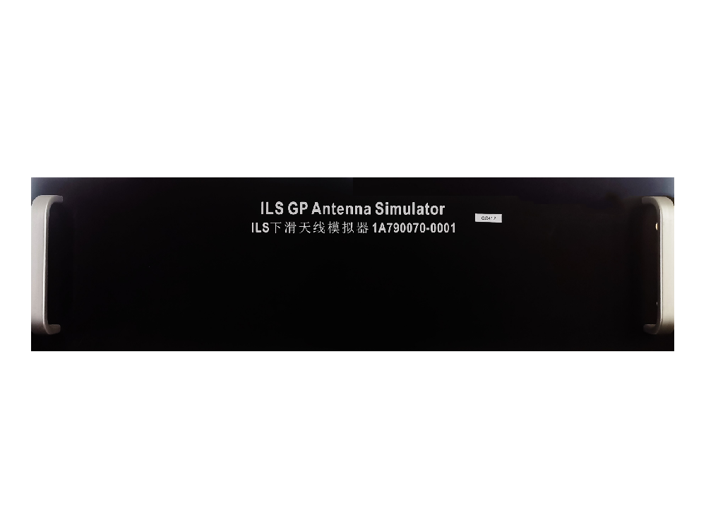
描述: The glide path beacon antenna simulator developed, produced, and sold by our company, model number 1A790070-0001, features a standard 3U chassis design for easy installation and simple connection, and is compatible with all types of glide path beacons.
GP Antenna Simulator,Model number 1A790070-0001, standard 3U chassis design, 48 cm wide x 13 cm high x 24 cm deep, easy to install, simple to connect.
Applicable equipment types: NM7000B, ILS2100, ILS410, ILS420, etc., all models of glide path beacons can be used.
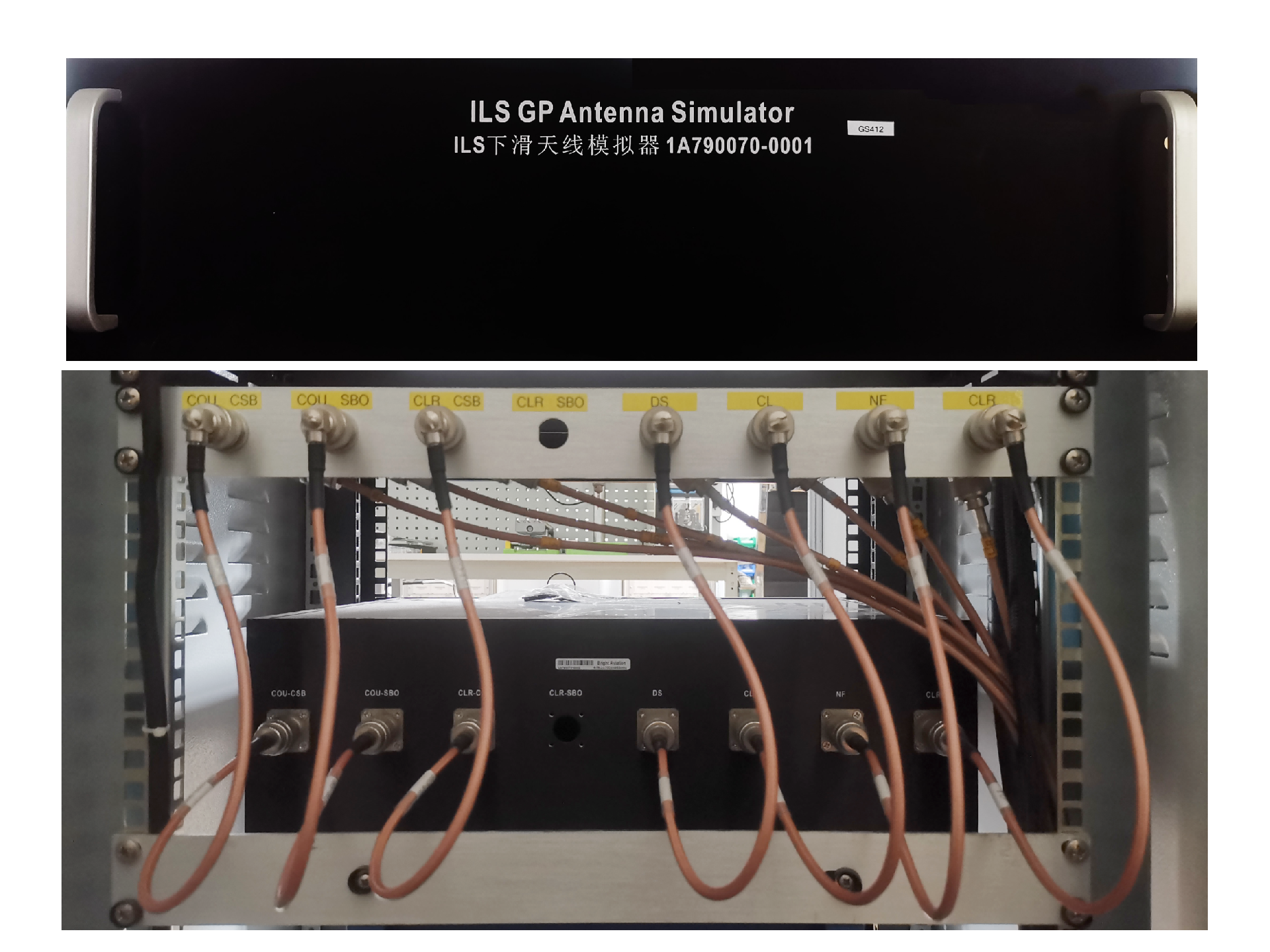
In the rear view of the GP Antenna Simulator, all connections are female N-type connectors, as shown in the figure below.
"COU CSB", "COU SBO", and "CLR CSB" are RF input terminals, which respectively connect to the three RF signals output by the glide path beacon master unit.
"DS", "CL", "NF", "CLR" are RF output terminals, representing four RF monitoring mixed signals output by the GP Antenna Simulator. "DS" represents the width RF monitoring mixed signal, "CL" represents the glide path RF monitoring mixed signal, "NF" represents the near field RF monitoring mixed signal, "CLR" represents the clearance RF monitoring mixed signal, and they are connected to the monitoring input terminals of the glide path beacon main monitor respectively.


 上一篇:
上一篇: 下一篇:
下一篇: