品牌: Bright Aviation,China
型号: ILS520,LLZ521,GP522
描述: “Bright Aviation” develops, produces and sells ILS520 Instrument Landing System (ILS).

Airport facilities and brand suppliers

- Navigation ILS DVOR DME MB NDB Antenna Simulator PIR Civil Aviation Equipment Central Shelter DVOR Antenna Reflector Network Fiberglass Flexible Rod Aviation Obstruction Light Network Transmission System Navigation antenna
- Communication
- Weather
- Surveillance
- Terminal
- Transmission
- Instrument
- Lighting
- Power Supply
- Other Projects
Product


520 Instrument Landing System (ILS)
一、Business
“Bright Aviation” supplies complete sets of equipment, including spare parts supply, installation and commissioning, flight check, panel repair, factory training, after-sales service, technical consultation, spare parts support, on-site fault repair, periodic inspection and other businesses.
二、Overview
1.Instrument Landing System(ILS) provides guidance information for airport approach and landing flight to align with runway center line and a 3°glide angle.
2.The equipment consists of LLZ521 Localizer, GP522 Glide-Path and remote controller.
3.Provide the most advanced technology and the most reasonable system architecture for the performance selection of ClassⅠ、Ⅱand Ⅲ equipment, and provide users with friendly Windows based The graphical software interface integrates, the latest technical features to reduce the number of system boards.
4.3U standard design reduces the cost of equipment installation, maintenance and logistics.Software design and certification meet the strict RTCA DO-178 B/278 standard.
三、Localizer(LLZ521)
(1)Electrical
1.Frequency Range:108~111.975MHz.
2.Modulation Tones:90Hz and 150Hz(Single tone Modulation Depth 20%),1020Hz(Modulation Depth 10%).
3.CSB Power Output:5~30W(0.01W step adjustable).
4.SBO Power Output:0.1~1W(0.01W step adjustable).
5.Frequency Stability:±0.0001%.
6.Frequency Control:Synthesizer.
7.Coverage: Meet ICAO Annex 10.
8.Monitors:Dual Parallel And/Or configuration,and built-in-test generator.
9.RMM Software:Local or remote operation equipment software.
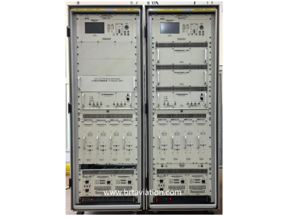
(2)Appearance
LLZ Cabinet | 12 Unit LLZ Antenna System (Including ADU and MCU) |
|
|


(3)Performance
1. Single and dual transmitter configurations (optional).
2. Single and dual frequency transmitter configurations (optional).
3. 12, 14, 16 and 20 unit LLZ antenna system (optional).
4. IP port of PC accesses RMM software of equipment.
5. Dual monitor configuration, cold or hot backup system configuration mode.
6. Automatic diagnosis of equipment failure, one click upload and download of equipment parameters.
7. One click printing of monitoring parameter report.
8. The IP port of the remote controller is connected to the ILS cabinet to monitor the working status of the equipment in real time.
9. The system can be upgraded from class I to class II and class III equipment performance at any time.
10. Primary Power:110~220Vac±15%,45~63Hz,single phase.
11. Standby Power:24Vdc backup battery,working for at least 4 hours.
(4)Mechanical
1.Weight:220kg.
2.Size: 170 (H) * 60 (W) * 60 (D) cm,35U cabinet.
(5)Environmental
1. Temperature: Indoor -10°C~+50°C, Outdoor -50°C~+70°C.
2. Relative humidity: Indoor 0~95% (non condensing);Outdoor 0~100% .
3. Altitude: 0~4500m MSL.
4. Work cycle: continuous unattended.
5.Wind speed conditions: the outdoor antenna can work normally when the wind speed is up to 161 km/h and the antenna icing is 1.5 cm thick.
(6)Equipment List
No. | Name | Model | Qty/Unit | Description |
1 | LLZ Cabinet | LLZ521 | 1 Set | Including dual frequency, dual transmitter, dual monitor, dual power supply system. |
2 | 12 Unit LLZ Antenna System | / | 1 Set | Including 1 set of Antenna Distribution Unit (ADU), 1 set of Monitor Combiner Unit (MCU), 1 set of 3m high antenna support system, 12 sets of transmission cables, 12 sets of monitoring cables, and 2 sets of obstruction light. |
3 | LLZ Near-Field Monitoring Antenna | / | 1 Set | Including 1 set of 1.5m high antenna support system, 1 LLZ near-field monitoring antenna, 1 monitoring cable and 1 obstacle light. |
4 | Other Accessories | / | 1 Set | / |
四、Glide-Path(GP522)
(1)Electrical
1.Frequency Range:328.6~335.4MHz.
2.Modulation Tones:90Hz and 150Hz(Single tone Modulation Depth 40%).
3.COU CSB Power Output:2~10W(0.01W step adjustable).
4.COU SBO Power Output:0.1~1W(0.01W step adjustable).
5.CLR CSB Power Output:0.2~1W(0.01W step adjustable).
6.Frequency Stability:±0.0001%.
7.Frequency Control:Synthesizer.
8.Coverage:Meet ICAO Annex 10.
9.Monitors:Dual Parallel And/Or configuration, and built-in-test generator。
10.RMM software:Local or remote operation equipment software.
(2)Appearance
GP Cabinet | M-Type GP Antenna System |
|
|


(3)Performance
1.Single and dual transmitter configurations (optional)。
2.Single and dual frequency transmitter configurations (optional)。
3.M-type capture effect GP antenna system。
4.IP port of PC accesses RMM software of equipment。
5.Dual monitor configuration, cold or hot backup system configuration mode.
6.Automatic diagnosis of equipment failure, one click upload and download of equipment parameters。
7.One click printing of monitoring parameter report。
8.The IP port of the remote controller is connected to the ILS cabinet to monitor the working status of the equipment in real time。
9.The system can be upgraded from classⅠ to class Ⅱ and class Ⅲ equipment performance at any time。
10. Primary Power:110~220Vac±15%,45~63Hz,single phase.
11. Standby Power:24Vdc backup battery, working for at least 4 hours.
(4)Mechanical
1. Weight:200kg.
2. Size:170 (H) * 60 (W) * 60 (D) cm, 35U cabinet.
(5)Environmental
1. Temperature: Indoor -10°C~+50°C, Outdoor -50°C~+70°C.
2. Relative humidity: Indoor 0~95% (non condensing);Outdoor 0~100% .
3. Altitude: 0~4500m MSL.
4. Work cycle: continuous unattended.
5.Wind speed conditions: the outdoor antenna can work normally when the wind speed is up to 161 km/h and the antenna icing is 1.5 cm thick.
(6)Equipment List
No. | Name | Model | Qty/Unit | Description |
1 | GP Cabinet | GP522 | 1 Set | Including dual frequency, dual transmitter, dual monitor, dual power supply system. |
2 | GP Antenna System | / | 1 Set | Including 1 set of M-type GP antenna distribution unit (ADU), 1 set of M-type GP monitoring hybrid unit (MCU), 1 set of 15m high GP antenna tower, 3 sets of transmission cables, 3 sets of monitoring cables, and 1 set of Obstruction light. |
3 | GP Near-Field Monitoring Antenna | / | 1 Set | Including 1 set of 5m high antenna support, 1 GP near-field monitoring antenna, 1 monitoring cable and 1 obstacle light. |
4 | Other Accessories | / | 1 Set | / |
六、Remote Controller and Repeat Display Unit
(1)Appearance
Remote Controller(Navigation Duty Room) | Repeat Display Unit(Tower) |
|
|


(2)Electrical
1. The remote controller communicates with the ILS equipment through the Ethernet IP interface.
2. The remote controller communicates with the repeating display unit through RS-485 protocol.
3. Primary Power: 110~220Vac±15%, 45~63Hz, single phase.
4. Standby Power:24Vdc backup battery, working for at least 4 hours.
(3)Mechanical
1. Weight:4kg.
2. Size: 13.4 (H) * 60 (W) * 20 (D) cm, 3U chassis.
(4)Environmental
1. Temperature: Indoor -10°C~+50°C.
2. Relative humidity: 0~95%.
3. Altitude: 0~4500m MSL.
(5)Equipment List
No. | Name | Model | Qty/Unit | Description |
1 | Remote Controller | / | 1 Set | 3U chassis,Mounted in the navigation duty room of the ATC Building. |
2 | Repeat Display Unit | / | 1 Set | 3U chassis,Mounted on the tower control desk panel of the ATC building. |
3 | Transmission Equipment | / | 1 Set | / |
4 | Other Accessories | / | 1 Set | / |
七、RMM Software
The RMM software interface provides Chinese and English operating languages to facilitate user operation and maintenance of equipment, as shown below.
LLZ“Monitoring Unit”Interface (Chinese) | LLZ“Monitoring Unit” Interface (English) |
|
|


八、Meeting Standards
1. CAAC,《Aeronautical radio navigation aids,Part 1:Technical requirements for Instrument landing system (ILS)》, MH/T-4006.1-1998.
2. CAAC,《Electromagnetic environment requirements for aeronautical radio navigation stations 》, GB 6364-2013.
3. CAAC, 《Specification for aeronautical communication navigation and surveillance station siting criteria,Part 1: Navigation 》, MH/T 4003.1-2021.
4. CAAC,《Test Requirements for Aviation Radio Navigation equipment,Part 1: Instrument Landing System》, AC-115-TM-2013-01。
5.CAAC, 《China civil aviation instrument landing system classⅡoperation regulations》, CAAC order No.57.
6. ICAO, Annex 10, Aviation Telecommunications, Volume 1, 《Requirements for Radio Navigation equipment》.
7. ICAO, Document 8071, Volume 3, 《Test Manual for Radio Navigation equipment》,(1972).
九、Comparison
Some technical indicators of ILS520 type ILS equipment are compared with ICAO Annex 10 and CAAC ILS equipment technical requirements, as show below.
No. | Technical Index Content | ICAO Annex 10 | CAAC | ILS520 Equipment |
1 | LLZ Carrier: Frequency Tolerance | ≤±0.0004% | ≤±0.0002% | ≤±0.0001% |
2 | LLZ (ClassⅠ) :Single Tones 90Hz and 150Hz Frequency Tolerance | ≤90Hz±2.5%; ≤150Hz±2.5% | ≤90Hz±1.5%; ≤150Hz±1.5% | ≤90Hz±0.5%; ≤150Hz±0.5% |
3 | GP Carrier: Frequency Tolerance | ≤±0.0004% | ≤±0.0002% | ≤±0.0001% |
4 | GP (ClassⅠ) :Single Tones 90Hz And 150Hz Frequency Tolerance | ≤90Hz±2.5%; ≤150Hz±2.5% | ≤90Hz±1.5%; ≤150Hz±1.5% | ≤90Hz±0.5%; ≤150Hz±0.5% |
Note: By comparing the results, some technical indicators of the ILS520 equipment are better than the technical standards of ICAO and CAAC.
 上一篇:没有了!
  下一篇:
下一篇: