Brand: Bright Aviation,China
Model: NDR-8800
Description: “Bright Aviation” sells VCS-8800 series Voice Communication System.

Airport facilities and brand suppliers

- Navigation
- Communication Automatic reporting equipment Information Process System VHF Communication Radio VHF radio auxiliary equipment Recorder Intercom System Ground Intercom System Video Surveillance System Cabinet
- Weather
- Surveillance
- Terminal
- Transmission
- Instrument
- Lighting
- Power Supply
- Other Projects
Product


VCS-8800A Voice Communication System (Interphone System)
一、Business
"Bright Aviation" supplies complete sets of equipment, including spare parts supply, installation and commissioning, technical guidance, factory training, after-sales service, plate repair, spare parts support, equipment fault repair,periodic inspection and other businesses.
二、Overview
Voice Communication System is connected to the voice and control signals of VHF radio and telephone respectively, providing the airport air traffic control department (ATC) with a fast, convenient and highly reliable voice communication system (VCS), which is convenient for multi seat controllers to dispatch, command, use and manage the working frequency of multi-channel VHF radio, as well as multiple telephone communication scheduling.
The system is a soft switch distributed architecture, which ensures the interconnection of the system in reliability, sound quality, delay and other key parameters in design.
三、Advantages
1. High Reliability: dual IP systems are independent and parallel, distributed call control, independent dual networks, isolated internal and external networks, redundant design, etc., to ensure that equipment has 99.9999% high reliability and availability.
2. Sound Quality Is Good: seat terminal, telephone board (CO), trunk board (PSTN) and other boards support echo cancellation algorithm to effectively reduce and eliminate spatial echo and line echo. EQ equalization processing is used to ensure that the voice of the controller is soft and the voice is clearer and fuller.
3. Lower Delay: ultra short packet switching is adopted, PTT response time ≤ 10ms, transmission delay from seat audio to radio interface board (IDF): analog radio ≤ 30ms, IP digital radio ≤ 15.5ms.
4. Strong Scalability: The system can be expanded by adding boards, plugins, cabinets, etc. It is very convenient to add hardware configurations through modular design.
5. Interconnection: meet the requirements of analog/digital radio, voice recorder, PSTN, The communication connection between VCS systems meets the specification requirements.
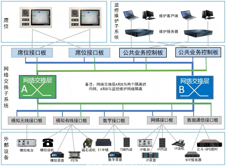
三、Architecture

四、Composition
1. Cabinet
(1) Cabinet: one 42U communication cabinet, one or more expansion cabinets and patch panel cabinets. As shown below.

(2) Typical Configuration (from top to bottom): AC power supply unit, DC power distribution unit, air guide unit, board card box, fan unit, network switching unit, monitoring and maintenance unit.
(3) AC Power Supply Unit: 4U, 2 sets of AC power supply.
(4) DC Distribution Unit: 3U, including 18 DC switches, power supply of control board card box and fan unit.
(5) Board Card Box: 4U, each board plug-in box provides 16 plug-in slots for installing various interface boards.
(6) Fan Unit: 1U, including fan control board, fan guide frame and fan chassis.
(7) Air Guide Unit: 1U, including air guide plate.
(8) Network Switching Unit: 2U, including two sets of switches A and B.
(9) Monitoring and Maintenance Unit: 4U, including 2 sets of monitoring and maintenance servers.
(10) The switch is front outgoing line, and other equipment is rear outgoing line
2. Board Card Box
(1) Board Card Box, as shown below.

(2)List of Boards Built In Board Card Box (Optional)
No. | Plate Model | Abbreviation | Description |
1 | Plug Box Backplane | BKRJ | Provide two DC power inputs. |
2 | Public Service Dashboard | CSCU | It is responsible for system call routing and system management, configuration storage, and is not responsible for call control. Each board is inserted into one box. |
3 | Plug Box Exchange Control Board | RSWU | Connect the interface board to the A/B network. Each board is inserted into 2 boxes. |
4 | Seat Interface Board | NPIF | Connect seats. Each board provides 4 seat interfaces. |
5 | Data Communication Interface Board | DCIF | Monitor AC power supply unit and fan unit. Access timing (one channel for serial port and one channel for network), node connection (two in and two out). |
6 | Analog Wireless Interface Board | ARIF | Connect E&M analog VHF radio, 2 channels per board. |
7 | Network Wireless Interface Board | NRIF | Connect the VoIP digital VHF radio, 16 channels per board. |
8 | Telephone Interface Board | ASIF | Connect a 2-wire telephone (CO) with 2 channels per board. |
9 | Loop Interface Board | ATIF | Loop connection PSTN/PABX, 2 channels per board. |
10 | Magnet Interface Board | ALIF | Connect the magneto phone, with 2 channels per board. |
11 | Network User Interface Board | NSIF | Connect the SIP phone, 16 channels per board. |
12 | Digital Networking Interface Board | DIIF | Connect ATS QSIG, G.728, 2 circuits per board. |
13 | Network Networking Interface Board | NIIF | Provide ED137 networking capability, 16 channels per board. |
14 | Centralized Recording Interface Board | CRIF | Provide system IP recording interface, 60 channels per board. |
15 | Analog Multi Frequency Interface Board | AMIF | Support E&M and MFC-R2 signaling interfaces, with 2 channels per board. |
16 | Digital Trunk Board | DTIF | Support ISDN PRI (base group rate interface) 30B+D, 30 × 64 kbit/s voice signal. |
3、Seat terminal
1. Composition: host (including panel), speaker, jack box, handheld microphone, headset, foot PTT key, power adapter. As shown below.

2. Seat processor: quad core Cortex-A53 chip, Linux operating system, 12.1 inch LCD, 1024 × 768 resolution, capacitive touch screen.
3. Maximum power consumption: ≤ 50W.
4. Number and type of interfaces:
(1) Power supply: 2+24V DC power interfaces.
(2) Communication interface: 2 RJ45. Analog recording interface: 2 RJ45. IP recording interface: 2 RJ45.
(3) Jack box: It supports up to 3 jack boxes, and each jack box has 2 LEMO 10 core sockets.
(4) Foot key interface: 1 jack box provides foot key connection.
五、Performance
1. System Capacity Index:
(1) Number of seats: ≤ 512.
(2) Analog radio capacity: ≤ 1024. VoIP radio capacity: ≤ 1024. Telephone subscriber capacity: ≤ 1024.
(3) Analog trunk capacity: ≤ 1024. Digital trunk capacity: ≤ 1024.
2. System Time Performance Index:
(1) A/G PPT response time: ≤ 10ms. A/G communication establishment time: ≤ 31ms. G/G communication establishment time: ≤ 102ms.
(2) Delay time of seat audio to IDF transmission: analog ≤ 30ms, IP digital ≤ 15.5ms.
(3) System cold start time: 5 ≤ minutes.
3. Reliability Index:
(1) System MTBF: ≥ 103428 hours, system MTTR: ≤ 20 minutes, system reliability: ≥ 99.999%.
(2) MTBF of seat terminal: ≥ 44232 hours, MTTR of seat terminal: ≤ 20 minutes, reliability of seat terminal: ≥ 99.999%.
六、Equipment List(4 seat configuration)
No. | Name | Model | Qty/Unit | Description |
一、Cabinet Configuration | ||||
1 | VCS Cabinet | / | 1 Set | 42U。 |
2 | Network Switching Unit | / | 2 Set | / |
3 | Monitoring and Maintenance Unit | / | 2 Set | / |
4 | AC Power Supply Unit | / | 2 Set | / |
5 | DC Distribution Unit | / | 1 Set | / |
6 | Board Card Box | / | 1 Set | / |
7 | Fan Unit | / | 1 Set | / |
8 | Air Guide Unit | / | 1 Set | / |
二、Board Configuration (Board Card Box, Built-In) | ||||
1 | Plug Box Backplane | BKRJ | 1 Pcs | Provide two DC power inputs. |
2 | Public Service Dashboard | CSCU | 1 Pcs | One card is embedded in each card box. |
3 | Plug Box Exchange Control Board | RSWU | 2 Pcs | Each board is inserted with 2 pieces. |
4 | Seat Interface Board | NPIF | 1 Pcs | Each board shall be provided with 4-seat interface. |
5 | Data Communication Interface Board | DCIF | 1 Pcs | Monitor the AC power supply unit, fan unit and access timing (1 channel for serial port and 1 channel for network). |
6 | Analog Wireless Interface Board | ARIF | 1 Pcs | Connect E&M analog VHF radio, and each board is connected with 2 channels. |
7 | Network Wireless Interface Board | NRIF | 1 Pcs | Connect the VoIP digital VHF radio, and each board is connected to 16 channels. |
8 | Telephone Interface Board | ASIF | 3 Pcs | Connect a 2-wire telephone (CO interface), and each board counts as 2 lines. |
9 | Network Networking Interface Board | NIIF | 1 Pcs | ED137 networking capability is provided, and each board has access to 16 channels. |
10 | Centralized Recording Interface Board | CRIF | 1 Pcs | Provide system IP recording interface, and each board is connected to 60 channels. |
三、Seat Terminal Configuration | ||||
1 | Seat Terminal | / | 4 Set | Including host (including panel), display screen, speaker module and jack box. |
2 | Hand Microphone | / | 4 Set | / |
3 | Headphones | / | 4 Set | / |
4 | Handle | / | 4 Set | / |
5 | Foot PTT Key | / | 4 Set | / |
6 | AC adapter | / | 4 Set | / |
四、Others Configuration | ||||
1 | Maintenance Monitoring Terminal | / | 1 Set | Server。 |
2 | Expansion Enclosure | / | optional | / |
3 | Distribution Frame Cabinet | / | optional | / |
4 | Wiring and Accessories | / | 1 Set | Including IDF distribution frame, lightning arrester, cable and auxiliary materials. |
七、Mechanical
1. Weight:180kg.
2. Size: 42U chassis,180(H) * 60 (W) * 100 (D) cm.
3. Primary Power:110~220Vac±15%,45~63Hz,single phase.
八、Environmental
1. Temperature: Indoor -10°C~+50°C.
2. Relative Humidity: Indoor 0~95% (non condensing).
3. Altitude: 0~4500m MSL.
4. Work Cycle: Continuous Unattended.
九、Application
Wudangshan airport , Wugang airport and other China airports.
 Previous:没有了!
  Next:没有了!