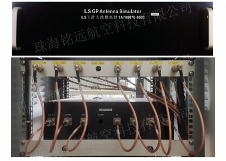
GP Antenna Simulator
型号: 1A790070-0001
描述: The RF carrier signal output by the glide-path host is connected to the GP antenna simulator. The antenna simulator is not only used as a transmission load (instead of the GP transmission antenna function), but also coupled and mixed output RF monitoring signals (instead of the GP monitoring antenna sampling RF signal function), ultimately making all monitoring parameters of the GP equipment monitor work normally.
Product Overview
Instrument Landing System (ILS), ILS equipment includes course beacon (LLZ) and glide-path (GP). The RF carrier signal output by the glide-path host is connected to the GP antenna simulator. The antenna simulator is not only used as a transmission load (instead of the GP transmission antenna function), but also coupled and mixed output RF monitoring signals (instead of the GP monitoring antenna sampling RF signal function), ultimately making all monitoring parameters of the GP equipment monitor work normally.
Product Characteristic
1. Applicable to all ILS equipment models (ILS520, NM7000B, ILS2100, ILS410, ILS420, etc.).
2. The average RF power input range of the glide-path CSB is 1W to 15W, the average RF power input range of the SBO is 0.1W to 0.5W, and the output range of the monitored RF signal is 10dBm to -40dBm.
3. RF and monitoring signal connector model: N-type female.
4. Three RF signal input connection ends are marked as COU CSB, COU SBO and CLR CSB. 4-channel RF monitoring output signal, marked as DS, CL, NF, CLR.
Product Appearance

MECHANICAL
Size:13cm(H)X60cm(W)X24cm(D),Standard 3U chassis.
Weight:5kg.
ENVIRONMENTAL
Temperature:Indoor -10°C— +50°C.
Relative Humidity:0 — 95%.
Application Airport
Yinchuan in Qinghai, Yantai in Shandong, Mangshi in Yunnan, Guilin in Guangxi, Hohhot in Inner Mongolia, Guiyang in Guizhou and other airports.


.png)
 上一篇:
上一篇: 下一篇:
下一篇: